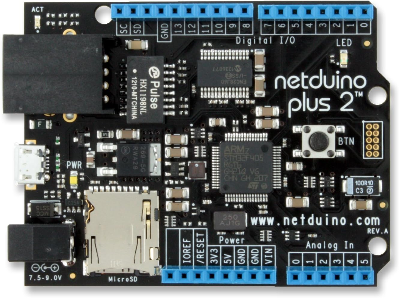

Netduino Plus 2
Product ID: 2058191
⚡168MHz Speed
💾384KB Storage
🧠100+ KB RAM
🚀 Elevate Your Projects with Netduino Plus 2!
The Netduino Plus 2 is a powerful microcontroller featuring a 168MHz Cortex-M4 MCU, 384KB of code storage, and over 100KB of available RAM. With 22 GPIOs, multiple communication protocols, and support for MicroSD and Ethernet, it’s designed for both hobbyists and professionals looking to create innovative projects with ease.
| ASIN | B009QOYK2U |
| Customer Reviews | 4.0 4.0 out of 5 stars (42) |
| Date First Available | November 7, 2012 |
| Item Weight | 0.96 ounces |
| Item model number | NetduinoPlus2 |
| Manufacturer | SECRET LABS |
| Package Dimensions | 5.5 x 4 x 2.4 inches |
J**N
Netduino verse Arduino
The Netduino Plus 2 is the latest version of the Netduino board. A Netduino is similar in layout to an Arduino UNO (AVR processor based prototyping board) but uses a 3.3 V 168 MHz 64 bit ARM7 processor instead of the 5 V 16 MHz 8 bit AVR processor the Arduino uses. There is an Arduino DUE board which uses a 3.3 V 84 MHz ARM processor but it is not 5 V tolerant so it cannot be used with 5 V shields while the Netduino is 5 V tolerant and should work with most 5 V shields. The Netduino also has built-in Ethernet and SD Card hardware and software support so no extra shields are required. The Netduino I/O pins are 5 V tolerant so it should work with most 5 V Arduino shields. What the Netduino does not have is the ability to directly use Arduino libraries. This is because the Netduino is programmed in C# using Visual Studio 2010 while the Arduino is programmed in C/C++ programming using their own IDE. The combination of C# and VS is very powerful and allows full debugging capabilities. The Arduino IDE is fairly limited and only allows "print" style debugging. Where the Arduino programming environment out shines the Netduino is in libraries written by others. Using these much of the code you would otherwise need to write (to operate an LCD display, talk to an I2C device, etc.) is already written and debugged for you. The Netduino .NET micro framework does have 3rd party code available, just not as much. The Netduino also suffers from a lack of support (as of this writing) by Microsoft. While they did make the .NET micro framework open source they have not kept it as up to date as the full blown .NET framework. For example, the micro framework still requires VS 2010 while the .NET framework uses VS 2013. Not a deal breaker (VS 2010 Express is free) but still something to consider if you program using VS 2013 regularly. So in summary the Netduino is a faster more capable alternative to the Arduino UNO/MEGA/DUE boards. If you like VS then it is definitely for you. It supports manage C# code as well as multitasking and has Ethernet capabilities built in. If your needs are much simpler and you don't need a full IDE then the Arduino may be a better choice. As a side note, the Netduino is designed to be completely open source / design. Since it has a built in ISP header it can be programmed directly like the Arduino. That is, you do not have to use the Microsoft .NET micro framework and could directly program the device yourself using open source tools. UPDATE (10/29/2014): As J. Madison points out there is now Visual Studio 2012 and 2013 support plus experimental 2014 support. the firmware on the Netduino is unchanged, but the PC tools and Visual Studio support has been split. This also means that you can install the Netduino SDK on VS 2010 and VS 2013 at the same time. Hopefully Microsoft will continue work on this power prototyping tool and keep the firmware up to date as well.
D**.
(!Net)duinoPlus2 = Bare-Metal Power House
I titled this (!Net)duinoPlus2 because my first order of business was to nuke the .Net framework and setup a bare metal library for it. I have been working on a midi interrupter project for a Tesla Coil and was previously using around 20+ Arduino ProMini boards with the ATmega328P micro, running in parallel -- mainly to have enough timer compare channels. But recently I wanted to super-size that with even more capabilities and rather than double or triple the number of processors needed, I opted to use a low-end Xilinx Spartan-6 FPGA to do the timer compares and feed it with a single microprocessor. A single FPGA board (available from Numato Labs here on Amazon for around $40) was capable of doing the timer compare logic of over 85 of the ProMini boards and at 6.25 times the timer clock speed, and just needed to be paired with a micro to feed it. Initially for the single micro feeding the FPGA, I tried an Arduino Uno, since I had a couple on hand and the code could run with very few modifications from what I had on the ProMini boards, plus it has readily available proto-shields and such for building the interfaces. But I quickly realized the Uno was falling way short of processing power to even simply push the data to the FPGA fast enough. So I needed a solution in the same basic footprint, only with more processing power. Even the other Arduino variants, while better, still wouldn't have been fast enough. Then I found this little board. PERFECT! But, I didn't want all of the overhead of the .Net framework plus didn't want to rewrite all of my code from C/C++ into C#. So the first thing I did was to take the .net framework source code and extract the basic hardware abstraction and peripheral access layers that were already tailored to this board (i.e. basic GPIO setup, clock initialization, SPI and USART transceiver logic, etc), and made a static-link library that would let me use this board as a bare-metal target. While it took me a couple of weeks to rework the framework into just a HAL/PAL library (of which I'm still working on), once I had enough of that done, it took me all of about 10 minutes to port my Arduino Uno/ProMini code to this micro. I simply deleted all of the Arduino specific low-level port setup code and replaced function calls for things like USART init and SPI I/O port write functions with calls to the HAL/PAL functions for this processor. The resulting code, even with modest C Runtime overhead (was using "newlib"), was only around 34K in total size -- and this micro has 1Meg of flash! (BTW, the similar code on the ATmega was nearly 20K.) This processor is a real power house. It has to be, or it couldn't run the .net framework in the first place (which is a huge overhead). I can't speak to its performance with it running the .net framework, but if you want to use it for bare metal programming, it's fantastic and is quite the powerhouse of a processor. I do wish it would have come with the GoPort soldered on for the JTAG. Not that it was difficult to solder on, but was one more setup step needed to get an in-system debugger up and running. For debugging, the ST-Link/V2 works well running with openocd (I only use Linux, BTW). I tried numerous debugger front-ends with it. KDbg worked, but had difficulties following the source tree well. And DDD kept crashing on me. But the best in-system debugger for it, hands down, is Eclipse. I use QtCreator for my IDE and normally it does an excellent job with debugging, but strangely I could never get it to work with the GDB from the arm-eabi cross-compiler. I think it was related to the Python scripting, which Creator needed, but Eclipse didn't -- even after rebuilding GDB and adding Python scripting support it still wouldn't work. With Eclipse and the ST-Link/V2, you can easily single step through your code and quickly debug issues. I had some linker script problems with the C-Runtime and the .init section and its running of static constructors that was causing it to hard fault during the bootup process. Having a good in-system debugger was very valuable and it worked well to track that down. While you can use the JTAG port for programming, for general programming during development, the DFU (direct firmware update) utility in conjunction with the ST bootloader (already programmed into this micro) works very nicely and is much more convenient. Just install the dfuload utility (you'll likely need to compile the latest version from source, as the one with most Linux distros is old and quite buggy). Then when you want to program it, hold down "the button" on this board and reset it, by either unplugging and replugging it on the USB or use a reset button on an attached shield. That will boot ST's bootloader and you can launch dfuload to program it. Though this brings me to my main two complaints on this board -- 1) "the button" (which is really nice in its functional design) is mounted at an awkward location. When you have a shield board plugged on top, it's really difficult to press it to switch it to bootloader mode. I had to use a pen-cap (since it was plastic and wouldn't short anything out) to slide between the boards and fish around until I found the button. and 2) there's no real "reset" button on the board. Now, 99% of the Arduino shields have a reset button, so this isn't too major, but it would be nice to have a reset button on this board that can send a hardware level reset in addition to this button to select whether you want to go into bootloader or not. i.e. it needs two buttons. But, these are both minor issues because once you have it programmed, except for development work, how often do you need to launch the bootloader? And for the reset function, most shields have a reset button anyway. On the plus side, I REALLY like how the power to the header pins (as well as each on-board peripheral) is controllable via software. Each has a dedicated transistor that lets you cycle power to any piece of it you wish and/or power down unused peripherals to save power. This worked really well for my FPGA application because I can simply cycle power to the header pins and force a low-level reset of the FPGA to force it to reload from its bootflash without resetting the STM32 itself. This also worked well during development and testing of the FPGA code -- no unplugging and replugging needed. The only real headache I encountered was in the interfacing of the FPGA to the STM32F405... I was hoping since both run at 3.3v I wouldn't need any buffers or voltage shifters or anything. I was using a SPI interface to communicate to the FPGA and even with extensive clock-domain synchronization logic, they still wouldn't communicate. It turned out to be lots of noise on the signals coming from the STM32F405 on this board. Now, a lot of that was probably due to it still being on a prototype circuit with long wire runs that will go away when I do the final PCB turn. But in any case, I had to use a buffer chip between them, when I really shouldn't have needed anything. And yes, I tried every combination of pull-ups and pull-downs and pin configuration options and logic types, etc. The only thing that resolved it was adding a buffer chip (like is used in voltage-level shifters) and then it communicated flawlessly. And it was definitely noise and general lack of output drive from this board and not just a speed related issue, as I tried slowing down the SPI clock to a crawl and that made no difference whatsoever. So what I'm getting at there is that the I/O pins on this micro don't seem to have the same drive capabilities of the lower powered ATmega parts, etc, meaning you may have to consider your interfaces and connected devices more closely -- and it probably means that some shield boards may simply not work with this board without modification (not sure). All in all, for a board that has a common footprint with lots of stackable boards and accessories for prototyping and small project design, it's hard to beat this. I couldn't find any better processor for the dollar in the same profile and footprint. Though having said all of that, it's a pretty huge leap to go from bare-metal programming on an ATmega to bare-metal programming on a STM32. So if you've never worked with manual port configuration, writing linker scripts, writing device driver code, etc, you should get your feet wet first on a smaller micro. Otherwise, I highly recommend this board. The design was well thought out and I/O mapping is pretty optimal. And even the interfaces back to the Arduino header, as it's mapped out to specific peripherals and certain I/O pins, was done well. Update: I forgot to mention ... for the JTAG connector, you can search for "goport" here on Amazon and find it. But spec-wise, it's a 10-pin (2x5) header connector with 0.050" center pins. You can use shrouded or unshrouded. The shrouded is nice because you have a key for plugging it correctly, but the unshrouded is much easier to connect/disconnect. If you are using the shrouded version, the open or key side goes inward toward the microprocessor. There's a little teeny tiny white dot on the silkscreen marking pin 1, but at least on my board, that dot was literally on the apex of the corner of the silkscreen markings for the connector outline and impossible to see. You can easily ohm it out to verify orientation. Also, for the ST-Link/V2, you'll need a micro (or mini or whatever they call it) JTAG (10-pin) to standard JTAG (20-pin) adapter. Olimex has one. Search for "Olimex ARM Micro JTAG adapter" here on Amazon and you'll find it. It even comes with the little ribbon cable so all you have to do is plug it in. Update 2: I finally got around to interfacing this board with an I2C 20x4 LCD screen, and even though the I2C interface on the LCD is 5v and the I/O pins on the Netduino are 3.3v, since I2C is open-drain (and was configured as such), no voltage level shifter or buffer should have been required, as each device only has to pull the signals to ground and the Netduino's processor pins are 5v tolerant. But after much frustration of trying to get it to work without a level-shifter or buffer, I had to give in and add one. Then it worked fine. Though for I2C, it must be bi-directional and needs to be one like the SparkFun BOB-12009 using the MOSFET transistors rather than the TXB0104 chip version, as the I2C pull-up resistors messes up the direction switching logic of the TXB0104 chip and won't work. But the MOSFET version works great. But once again, I'm finding the I/O drive of the STM32F405 processor to be much inferior to that of other processors, like the ATmega328, which can interface that LCD (even with mixed voltages) without any level shifter. So expect to have to deal with needing to buffer I/O lines and do voltage conversions -- even in situations where it shouldn't be needed -- to get other devices and shield boards to work with the Netduino. While this is more a function of the STM32F405 processor itself and not specific to the NetduinoPlus2 board, this board fails to provide any on-board support to handle this. And that would be nice for a board claiming compatibility with Arduino Shields. I would drop it to 4 stars for this, but it's still a very nice higher-performance micro board for the buck. There are some voltage level shifter shields out there. I haven't tried them, but maybe they would work as a generic bridge between this board and add-on shields to make things work better? Though not sure if they would do well if you have mixed voltage devices -- as the FPGA I interfaced was 3.3v, and while it didn't need any voltage level shifting, it did need SPI I/O buffering. So expect some interfacing headaches... Update 3: I've now had time to write my own SD Card driver and FAT FS interface layer for it. And by the way, you aren't limited to a 2GB SD Card as the Netduino specs says -- that's merely a software limitation in their .net framework. Not sure why they limited it there, but elm-chan.org has a wonderful open source FATFS library that works up to 2TB and easily interfaces with SD Cards, ATA drives, USB drives, etc. Just provide it a low-level driver interface. I presently have mine reading and writing 32GB SD Cards, but not without a few interfacing headaches along the way, which brings me to this update... The problem is that the MISO SPI input pin on this Netduino has a pull-down resistor instead of a pull-up resistor. It has to have a resistor going one way or the other in order to satisfy the DFU bootloader and keep it from getting confused, as that pin is an alternate input for it. BUT, the problem with the pull-down is that the SD Cards come up in SD-Mode with all of its I/Os in open-drain mode. The idle state for the outputs is a '1' and during initialization, the SD card is expecting to pull it to ground to broadcast a '0'. The SD cards are free to output busy-bytes while its processing. The start of a good message begins with the first transition to a '0'. BUT, if your bus is pulled to ground, you can't see that!! Now, once the SD card is initialized and configured for SPI mode, that output becomes push/pull and the SD Card can drive it. But, as it is, it will cause you headaches with the initialization process. I was tempted to breakout my soldering iron and change it from a pull-down to a pull-up, but when I saw it was a 0201 size resistor and not wanting to have to do surgery on every future card I used, I decided to work around it in software instead. The workaround is to send out the SD Card CMD00 twice. On the first one, just cycle through enough SPI clocks as if you were really able to see and verify its results, but then toss it, and do it a second time. The first one will switch the card to SPI mode and then the next time you issue the CMD00, you'll be able to see the results from the SD Card since it will be configured push/pull. So, I don't fully understand why they chose a pull-down on that pin. But once I figured that out, I was able to crank up the speed (init should be done at 400kHz) and talk with the card at 21 MHz with no problems. My next issue with this board is that the VBat power input is tied directly to VDD, with no diodes or jumpers or anything isolating them. This means you cannot use the 4K battery-backed RAM option nor the Real Time Clock that this processor has, making those peripherals useless. With a little surgery, you could lift pin 1 (VBat) and put a jumper wire over to your backup power circuit. But, why couldn't they add something for that pin? I can see not wanting to incur extra expense in a diode or a connector, but they at least could have put a solder jumper bridge and a through-hole solder pad to where you could connect something there. So --- given all of these interfacing headaches, a lack of VBat connection point, etc, I've bumped my review down to 4-stars. It's still a great board and works really well with the newlib C-runtime and the libstdc++ packages. It's nice being able to work with an embedded microcontroller with STL, stdio, a real heap with malloc/free, etc, and still have all of the low-level I/O abilities. And with all of this, my code still hasn't broken over 100K yet! I still have 900K of free flash!
S**E
I was really disappointed in the Netduino Plus 2
This may be the 1st negative review I've ever written on Amazon. I was really disappointed in the Netduino Plus 2. I was hoping the increased memory and ability to code in C# would allow me to create some much more sophisticated logic for my project, but it just wasn't the case. In order for this thing to work, you need to get the right version of Visual Studio, the .net micro framework, the netduino SDK and the firmware on the Netduino. It is like getting all the planets to align at once. After many hours installing and re-installing, I finally found the right combination to be able to send programs to the device. The documentation on the website is not updated and you have to go to the forums to find what you need in terms of installation. Not impossible, but not very welcoming, compared to my experience with the Arduino Uno and Mega. Once I got Visual Studio working with the device, I had problems after every time or two, after updating the Netduino with my program. The device would basically fail to allow you to connect to it. To solve this I'd have to boot the device a special way and the run a program that cleared out the device's memory. Lame.... I even tried simple led blinking programs and had problems after the 1st or 2nd upload. After spending too many hours trying to get this running, the device is going in my junk electronics box. I don't care as much for the $ wasted, the time was my biggest loss. If you want to save yourself some time, just get a Mega and read and write to the SD card if you need to deal with larger amounts of data.
Trustpilot
1 month ago
5 days ago