


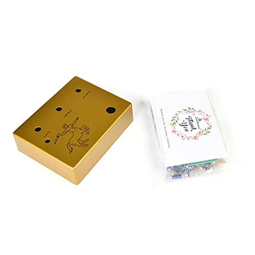

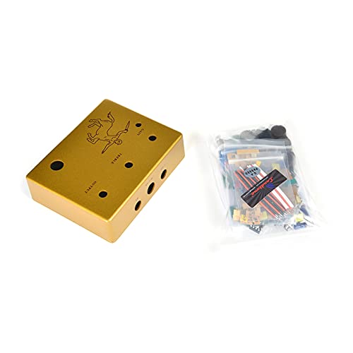

DIY Your Genuine Overdrive Guitar Effect Pedal All Kits US2
| Power Source | Adaptor |
| Controls Type | Knob |
| Signal Format | Analog |
| Voltage | 9 Volts |
| Color | Transparent |
| Style Name | Overdrive |
J**M
A challenging but nice build of a classic...
I like this kit. For some context, I was building kits from Radio Shack and Heathkit fifty years ago when I was 8 or 9 years old. I'm also a ham radio operator who builds and repairs a lot of gear. This is definitely not a kit for the novice, but overall I was impressed. The errors mentioned earlier about the diode needing a jumper and an issue with one of the caps seems to have been resolved. I tested parts of it with an ohmmeter to trace out those parts of the schematic and things were as they should be. Most components were within 5% tolerance (I measured every resistor and all of the non-electrolytic capacitors) with the exception of a few capacitors that were just a bit more. The only real error seems to be that the board really does seem to say 320P, not 820P for one of the capacitors. (I'm pretty sure it isn't just the edge of the 8 being drilled off for the hole.)The only think I can really add is to show how I believe the holes for stress relief on the 9 volt battery cable are supposed to go. (See the picture...) The other hint I'll offer is that the LED slides in and out of the threaded holder. It is much easier to get the leads through the circuit board before you set it in place and then use a pair of needle nose pliers on the leads to push it gently into the panel mount. (I couldn't get the legs in the holes doing it the other way. I tried the method I just described as a last ditch effort before I used some flexible wires to wire up the LED to the board.)I'm fairly new to the world of guitars and will say that this pedal's effects seem fairly subtle with my inexperienced use. It was an impulse buy (I normally use a modeling amp) so I didn't do a lot of research. But from what I have seen, it seems to behave just like the real thing. And it looks nice setting by my Les Paul Muse.Without the web page referenced by others, it would have been a lot tougher build. The instructions are now in color and on a large poster which helps. I built it over about two hours a day for two days. (And, like I mentioned, I tested the values of most components.) There are little things that tell me whoever put this kit together really wants it to be reasonably to build. One is the fact that the hookup wire comes pre-cut and pre-tinned. Someone just wanting to do things as cheap as possible would have just included a roll of wire for you to cut to length. (Heck, even Heathkit did that...) All of the resistors were marked but the decimal place on ones like 1.5K were hard to make out and so were the color codes. Measuring the resistors was the only way my old eyes were going to get things right. (And I do have a lighted magnifying glass I was using.)It worked when I powered it up the first time. It took more time and patience than a lot of other kits, but it is something pretty cool. I'm not sure how much use it will get, but I'm happy to add it to my growing collection of guitars and guitar paraphernalia!
D**Z
Great Kit, Great pedal. Not for beginners.
Great pedal kit. Instructions are mostly complete. (See below for supplementary instruction) They are accurate contrary to what you might hear on other reviews. This is no beginners project. The component density is pretty high. You must have a very good fine tip solder iron and DMM to be successful. Also helps to have a magnifying glass. I was sent a complete kit with very high quality components (except the knobs). All the resistors were labeled as to their value. It took me about 4 hours in 3 different sittings to complete because I took my time. The same company seems to sell a similar pedal on eBay for around $73. The Red Horsie. May be worth the $30 for them to build it for you!Pros:-Great sound- High quality components.- Looks greatCons:- Could be a difficult build depending on your skill level- Battery power is switched on output jack, not input jack like all other pedals on planet- No internal battery mount to keep the battery from rattling around inside I can't get over how good this pedal sounds. It is a very transparent overdrive with a wide range of drive level. From almost none to very crunchy. (Not a distortion pedal). Just makes the amp sound better. Does not seem to impart any flavor or coloration on it's own.Supplementary instruction: Make sure to install components on the same side as the silk screen. Pots and LED on one side, all others on the other. See pic.
D**D
Sounds amazing, would benefit from better instructions
I have now assembled two of these Klon clones from ProLandtone and I must say I am quite impressed. They sound phenomenal. As far as I can tell by studying the schematic for the Klon, this is an EXACT clone of the circuit. Yes, some components are cost reduced versions (i.e. the pots) but for the price, you cannot beat it. You get all that wonderful Klon tone for the cost of the kit plus a few hours of your time, which is way better than paying the $3,000+ they are going for on Reverb.com at time of writing. Even if you were to upgrade all of the components to be true to the original Klon spec and basically just used the board and the enclosure you would still come out WAY ahead of buying a pre-owned Klon.The instructions at first glance are very impressive. Minimal translation errors, very large, and very good diagrams. There are two major flaws with the diagrams though that will keep this from working for you on first assembly, plus a third minor flaw on the board itself that is more annoying than anything else.The first major flaw is the schematic for wiring the footswitch. In the diagrams that are drawn out, the switch is shown oriented with all pins on the switch horizontal, and eyelet holes 1 - 6 in the PCB connected to pins 1, 2, 3, 7, 8, 9, of of the switch (the top row and bottom row). This, however, will not result in a working pedal. Flipping the directions over to the other side is not much more help, as the wires are on the correct terminals now, just not in the right order. The proper way to wire the switch is as follows: 1 - 1, 2 - 4, 3 - 7, 4 - 3, 5 - 6, 6 - 9, where the first number is the eyelet number and the second number is the pin number on the switch when held with all terminals horizontal. Pin 1 on the switch will be top left-most pin, and pin 9 will be the bottom right-most pin. The easiest way to do this is to pick a three color pattern from the wires (for me it was red white black) and then repeat it. Then all you have to do is match colors horizontally across the switch.The second major flaw in the diagram is the input jack. The drawn diagram is really not good at all for either jack, especially the input jack. Assuming the white part of the input jack in the diagram is the 45 degree angled corner in the TRS jack, it has you make the connection to the tip and ring of the jack, and omits the sleeve, resulting in no output. Since the pedal only uses one TRS jack to control battery power draw and the other only uses the tip and sleeve, this problem would have been easily remedied by including one TS and one TRS jack in the kit, rather than two TRS jacks. To fix this, orient the jack with the pins facing toward you and the 45 degree corner in the top left corner. The bottom terminal will go to the left "IN" eyelet on the PCB, and the pin in the 45 degree corner will go to the right "IN" eyelet on the PCB.The third flaw that was more annoying than anything else was the markings on the board for the capacitors. Generally the board is marked extremely well as to what components go where. However, this is not entirely the case for the poly film capacitors. Most are marked by their capacitor code, which makes them fairly easy to find and install as the code is all that is printed on the capacitors. But six of the capacitors are marked by their capacitance value on the board on the side with the battery snap, requiring the use of a lookup website or experience with capacitors to figure out which of the capacitors go where. This isn't a major project ender for me, mostly a little annoying, but I could see it completely derailing someone who has little experience in electronics.Also, not sure why but one of the germanium clipping diodes (the 1N34As) shattered on me when I bent the lead to install it in the board of my second kit. This particular kit was slated to be a Christmas gift and luckily Amazon came in clutch and had the correct diodes available for next day delivery, but a component physically shattering under normal use to install it into a circuit board is really not good.At the end of the day, I highly, highly recommend this kit to anyone who wants that thick, rich, Klon sound but doesn't want to pay the insane amount of money they go for second hand. The kit is overall well designed with just a couple flaws in the instructions, but all of these DIY kits like this have some issue. The labeling of all the resistors is a very nice touch, and the fit and finish of the case is very good.Overall I rather like and enjoy this pedal more than just about any other overdrive I have ever used. And that includes the Plumes, Timmy, Tumnus, Boss OD-1, SD-1, Blues Driver, Gain Changer, and several others. Granted what works well for me in my set up may not work for you in your set up, but I've played this through a Joyo Blue Jay, Marshall DSL-40CR, and a Bugera 333XL and it sounds FANTASTIC on all of them. I've even used it with great success on a Fender Sidekick Switcher and Fender Frontman 212R, both of which are notoriously picky for what drive pedals will sound good with them. I've thrown humbuckers, single coils, P-90s, and Filtertrons through this thing and everything sounded great.If you've got the solder know-how and equipment, I highly recommend you try this kit.
A**N
Great sound. Printed circuit board required 2 jumpers.
This pedal sounds great. It came with no schematic, so I downloaded and printed out the revised schematic of April 15, 2009 (URL not permitted here). On completing the build, I observed that the buffered bypass worked OK (op-amp U1A on the schematic), but there was zero output when the effect was switched in. Tracing the circuit backwards from the output jack, I immediately observed that there was no continuity between PCB pad 5 (pole of Switch 1A) and the output jack. The buffered bypass signal was making it to the output jack via R26 anyway, but the effect output was not making it to the output via its equivalent resistor R27, so that told me there was a further problem and I kept tracing the circuit, having soldered in a short wire jumper between pad 5 and the pad to the output jack to fix the first problem. All the voltages (+V, -V, 2V and Vb) were measuring OK at their respective test points, but I observed that there was no continuity between the anode of D4 (1N4742) and ground, as the schematic indicated there should be. Soldering in a second short wire jumper fixed the problem and the pedal sprang to life.Judging from all the comments about how easy this pedal is to build, I can only conclude that there has been a production run of defective circuit boards, and this explains some of the negative comments—even from experienced builders—that the device does not work at all. I strongly recommend that prospective builders download the schematic and draw up a parts list, correlating the various components with the photocopy of the empty PCB that comes with the unit. As other reviewers have noted, there are a few component values that are different in the kit: The kit comes with an extra 1M resistor, which I labeled R31, right at the input immediately after the jack and before the first 10k resistor, R1—likely to prevent popping from C1 when plugging in. Second, R14 (the LED's current-limiting resistor) is 4k7 in the kit, vs 3k9 on the schematic, but this is trivial. R20 (422k on the schematic) is replaced by a 430k resistor in the kit—again this is trivial, and within 2%. Finally, the kit comes with a 3PDT footswitch, whereas the circuit needs only a DPDT, so I swapped it for a DPDT switch in my parts inventory. I'll keep the 3PDT for something that needs it. As another reviewer has noted, the switch is of lesser quality. Most good ones are stamped with RoHS,the manufacturer's logo and/or maximum current rating, but the one in the kit is completely blank.Having said all that, for well under $60 delivered (albeit 6 weeks after i ordered it), this pedal is a tremendous bargain and a great front end for a pedalboard. Highly recommended! I gave it only 4 stars because of the two "no-connections" on the PCB that called for the addition of wire jumpers.
T**
Sweet pedal, sounds amazing.
Like a real klon. It is easy to build. Happy to have it.
Trustpilot
2 months ago
3 weeks ago