


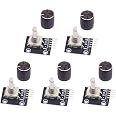
5pcs 360 Degree Rotary Encoder Module KY-040 Brick Sensor Development Board with Push Button for Arduino
Description
🔧 Turn Ideas into Reality with Precision!
- VALUE PACK - Includes 5 modules for extensive experimentation.
- INSTANT RESET - Easily reset to zero with a simple push of a button.
- PRECISION CONTROL - Ideal for stepper and servo motor applications.
- VERSATILE APPLICATIONS - Control everything from motors to digital potentiometers.
- UNLEASH YOUR CREATIVITY - Perfect for innovative projects with limitless rotation counts.
The KY-040 360 Degree Rotary Encoder Module is a versatile development board designed for Arduino enthusiasts. It operates at 5V and features a pulse count of 20 per rotation, allowing for unlimited counting in both directions. This package includes 5 modules, each equipped with a push button for easy resetting, making it the perfect choice for controlling stepper and servo motors or other devices like digital potentiometers.
Have a Question? See What Others Asked
Reviews
P**E
Built-in pull-ups
These rotors work really well for what I need. I had previously been using a rotary encoder I got from Sparkfun which worked, but it didn't have detents like these do. With the rotor in a detent, the rotor "CLK" and "DT" pins are disconnected from ground, so they get pulled to +5v just like "SW" when the button is not pressed. Spinning clockwise by one detent will pull CLK to GND first, then DT to GND, release CLK, then release DT. Counter-clockwise is obviously the reverse: DT low, CLK low, DT high, CLK high.Note that the image shows "5v supply", but all that's connected to is the 3 10k pull-up resistors that are connected to the two rotor contacts and the pushbutton. You could use any voltage you want to, or even swap 5v and ground so the pull-ups become pull-downs and the outputs are active high, or just leave it disconnected if you have external pull-ups.The pushbutton requires a bit more pressure than the other rotor, but it's hard to quantify.I connected all 5 to rotors (15 outputs in total) to a pair of PCF8574 GPIO expanders (with 8 GPIOS each). I connected the "CLK" pin of each to the first expander, and the "DT" pin to the second, then the INT line on both expanders to two GPIOs on the Raspberry Pi which are configured to interrupt on the falling edge - that way, even if there is a delay in reading the I2C bus, it still knows which way the rotor turned.The knobs appear to be anodized aluminum. I brushed the tops of the knobs and painted them with acrylic paint, then coated them with clear nail polish, and they look pretty good :)
E**S
I can't find any fault with this
The price is right, barely over $2 apiece. Construction is solid, and the pre-soldered pins make it super easy to prototype with. No matter how fast I spin it, it doesn't fail to register. (If you're getting missed steps, make sure you're using a high enough polling frequency, or--better--interrupt capable pins on your MCU!) The detents (the little bumps you feel while turning) are both smooth and well-defined. The encoder counts each bump as 4 units of rotation, and it does individually report the four positions in between bumps. So if you're using this for a menu interface and you want one bump to equal one menu item, you'll want to take that into account.You can push down on it to "click", and it feels nice and solid with a good audible clicking noise, down and up. The included knobs are not plastic--they're machined metal (aluminum?) and anodized black, with a visible marker which is etched into the top surface. The position of the marker is arbitrary, since the encoder has no minimum or maximum position--you can twirl it forever and it'll keep reporting how many notches you've passed (times four). The product description says something about returning it to zero with the click function, but that's entirely up to you. If you want that to happen, you'll need to program it. The encoder itself does not count or keep track of anything. It just sends the rotation and click-down signals to be handled by the MCU. This also means it can't tell you the absolute position of the dial. That's not a flaw, it's just how these products are designed to work.WIRINGThe two encoder pins are labeled CLK and DT; these are the ones you configure your MCU to watch for rotation events. The SW pin is the momentary click-in button. You need to supply 5v on the (+) and GND pins. I used the standard "Encoder" Arduino module on a Teensy 3.6 and it worked immediately. I initialized the Encoder instance with the numbers of the two pins connected to CLK and DT, and from then on all I have to do is call Encoder.read() to get the current value. Easy peasy.
C**N
Used to select LED output
Works great. Very fast shipping. Easy to interface with Seeeduino XAIO controller.
S**M
Works well, must set up accordingly on Raspberry Pi
The button clicks and works perfectly only when set up correctly on Raspberry Pi. If you are using GPIO pins and the GPIO module on the Raspberry Pi and programming in Python, you may see fluctuations and it may seem broken. Instead use evdev something like this...FIRST in terminalsudo nano /boot/firmware/confix.txt<then type in these lines replacing 17, 18, and 27 with the GPIO pins you use>dtoverlay=rotary-encoder,pin_a=17,pin_b=18,relative_axis=1dtoverlay=gpio-key,gpio=27,keycode=30,label="BUTTON"<save the file and reboot the pi>(Ctrl + O, Enter, Ctrl + X)sudo reboot<now you'll want to run evtest with >sudo evtest<and remember what event number the button and the rotary is and that's for your python code>~~~from evdev import InputDevice, ecodesimport selectrotary_device_path = "/dev/input/event4" # Adjust based on your system use evtest you can google itbutton_device_path = "/dev/input/event0" # Adjust based on your system#for handling (example is for increasing a counter and printing button status)def handle_rotary_event(event):global counterif event.type == ecodes.EV_REL:if event.code == ecodes.REL_X: # Rotary encoder relative movementif event.value > 0:counter+=1elif event.value < 0:counter-=1print(counter)def handle_button_event(event):if event.type == ecodes.EV_KEY and event.code == ecodes.KEY_A:if event.value == 1: # Button pressprint("button pressed")#then within a running loopwhile True:r, _, _ = select.select([rotary, button], [], [])for device in r:for event in device.read():if device == rotary:handle_rotary_event(event)elif device == button:handle_button_event(event)
B**N
Good quality
I like the "clicks" when rotating the knob :)
Common Questions
Trustpilot
1 month ago
3 weeks ago
