Desert Online General Trading LLC
Dubai, United Arab Emirates
Desert Online General Trading LLC
Dubai, United Arab Emirates


⚡ Keep your 16S pack perfectly balanced — because your power deserves precision!
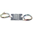
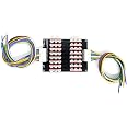
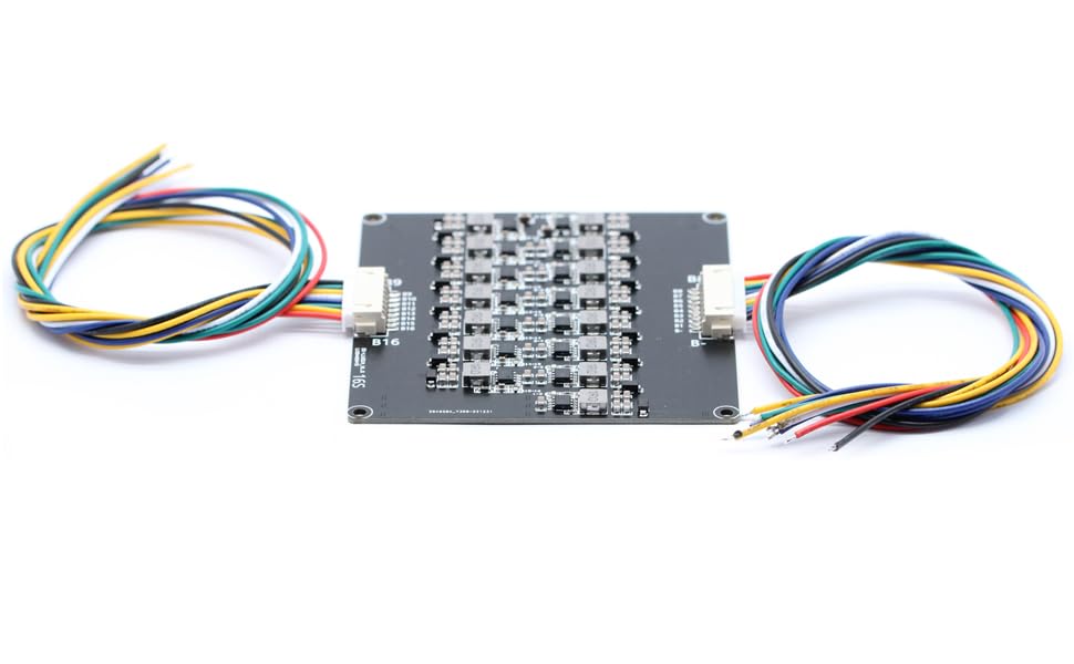
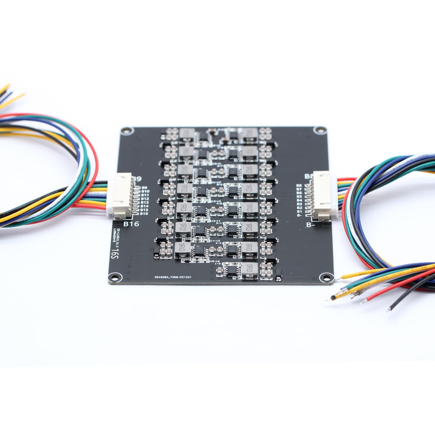
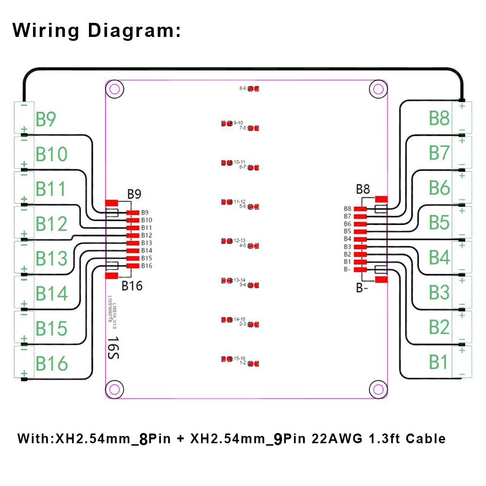
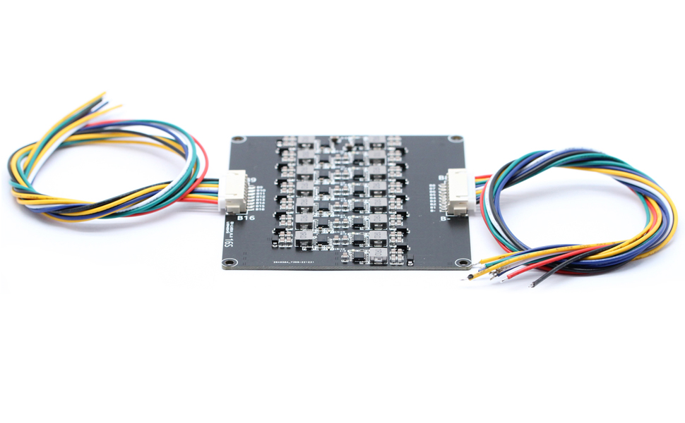
This 16S Active Equalizer BMS Balancer is a compact, high-efficiency PCB designed exclusively for 16S Li-ion and LFP battery packs. It intelligently balances cell voltages with up to 1.2A current, maintaining voltage differences within 30mV to optimize battery performance and longevity. Featuring smart LED indicators and ultra-low power dormant mode, it complements your BMS protection board by ensuring safer, longer-lasting battery packs.
O**V
Powerfull balancing current
Works perfect. Only camplait its how hot it can be when the cells very bad balanced, its realy powerfull balancer so thats why its become hot.100% worth money
B**R
Parasitic drain
Parasitic drain. I purchased these to use on starter batteries for small engines (tractors/generators). The batteries are discharged withing a few weeks! It's not the cells....it's this POS.
B**R
Works great but need to add BMS
This is my second build with this board. It dose what it says and all batterys stay within .001 of each other during discharge and within an hour or so after charging. Good quality has a coating that protects the board and keep it safe from vibration and moisture.
P**R
do not hook up black and red first ,
The media could not be loaded. Installed a month ago and the thing works great.But when I hooked up the first one. I hooked red+ and the negative on the other end first . With it plugged in and it caught on fire... So how you handel that is up to you
R**G
Inexpensive, compact Active Balancer to extend life of aging and new Ebike 13S Battery
March 17, 2025 Update: 2nd Balancer tested.These balancers breathed new life for my aging 48V 7.8Ahr ebike battery which suffers from high self-discharge imbalance issues. The second balancer will be integrated to my new 10Ahr Battery.Before for 500cycle Battery: only 20% capacity available due to imbalance. Multiple 'worn' batteries in the pack suffer from high self discharge and need to be individually charged to recover capacity.After: over 80% of original capacity available with Balancer constantly 'topping off' the weaker cells with high self-discharge.Key Balancer Requirements:1. Compatible with existing BMS (Battery Management System) including passive balance circuits.2. Very low standby (monitoring) current (0.01mA)3. Can balance over 3.0 to 4.2 Volt lithium battery range4. Has high balance current (.5 to .7A typical when Vdiff is between 0.1 and 0.2V)Balancer Review:1. Cost: Very reasonable price.2. Features: Status LED’s on PCB for each cell pair very helpful in debug and monitoring. Good Battery cell connectors and wiring harness. Size is small enough for most battery packs.3. Fit and Finish: Good. Balancer PCB components and traces are covered with protective film.4. Documentation: Inadequate. None supplied with product. Website instructions are somewhat sparse and awkwardly written.5. Installation: Straight forward but not error-tolerant. Significant time needed to thoroughly test all 12 circuits. Fourteen Balance wires need to be soldered while live to each of the 13 batteries in the correct order. Warning! Reversing Voltage polarity or shorting wires together may short out the TVS Protection diodes! (B0 should be 0V and B14 should be 46-55V).6. Quality: Needs improvement. Board #1 shorted out due to user wiring error which shorted 4 of the TVS Protection Diodes. Board #2 had 1 or 2 bad circuits (one cell position did not start balancing). Replacement board #3 and new #4 had no faults. One has to explicitly test each all 12 Balance circuits for balancing functionality.7. Performance: Good. Balance current 300-500mA with neighboring cell Voltage difference between 0.1 to 0.2A. Current of greater than 2000mA with a greater than 0.6V imbalance!8. Reliability: Short term good. Each of the 12 circuits are protected by a TVS protection diode and PCB surface-mount components appear robust and well protected (i.e. no electrolytic capacitors; all components are sealed and insulated). Continuous monitoring over a week: Pass800mA long-term balancing stress test: PassHow does this Inductive Active Balancer work? (See Attached Schematic)This 13 Lipo cell Balancer consists of 12 identical circuits which are individually connected across each of the 12 pairs of series connected battery packs. Each circuit has a 2cell Active BiDirectional Inductive monitor/balancer very low standby current IC. Each circuit continuously monitors the voltages and voltage-differences of the connected battery pair (running on a 2 second monitor/balance cycle). If a voltage difference of greater than 100mV is detected, the circuit switches it’s “charge-storage” inductor to the higher voltage battery and then switches the now-charged inductor to the lower cell which accepts the charge. This cycle repeats at about 1Mhz until the pair’s differential voltage is about 30mV. All 12 circuits are always ON (always monitoring their respective cell pairs) and can start balancing simultaneously during charge, discharge and storage.NOTE: Although each circuit independently monitor's it's dedicated cell pair, they are all daisy-chained together and synchronize their 2-second monitor/balance cycle. Therefore, all 12 circuits should be connected to the series connected 13S battery pack.Purpose of adding this Balancer to my Ebike Battery Pack:This Inductive Active Balancer was purchased to extend the life of the aged Battery pack (even the leaky cell pack had at least 80% effective charge capacity if recharged). It is wired in parallel to the existing BMS balancing wires and is expected to work in parallel with the BMS. Without the higher current Active Balancer, the high self-discharge cell would need periodic custom individual balancing.About the Lithium Ion Battery Pack used:The 48V 7.8Ahr pack consists, in this case, of 39 18650 LiPO 2.6Ahr batteries wired in a 3P13S parallel configuration. There is a BMS wired to the pack which controls discharging and charging and checks for Overtemp, UnderVoltage Overcurrent, and Overvoltage conditions. Each of the 12 series-wired cell packs are also monitored. The BMS supplied is capable of passive cell balancing through low current resistors whereby the higher voltage neighbor drains to the lower cell to equalize voltage. This balance circuit can only supply a few milliamps and works well until the cells begin to age and one or more start to exhibit abnormally high self-discharge (voltage leaks). If the integrated passive balancer cannot keep up, BMS limits the effective capacity of the pack to the lowest cell pack. Note that, for each 100mV imbalance difference, one loses about 10-20% of the effective capacity. In my case, the BMS of my 7.8Ahr 48V Ebike shutdown my pack after only about 1.5Ahr drain. This was caused by the low voltage (leaky) cell eventually dropping to less than about 3.0V while the other cell voltages were much higher. The BMS detected this undervoltage cell and switched the battery off.Installation and Checkout summary: (See photo)1. Installation. Before soldering the 14 balance wires from the connectors to the batteries: DO NOT Connect the two connectors to the PCB. It is also best if the battery pack is partially discharged.a. Starting with the B- (Black) wire (lowest voltage) solder each wire to each battery tab.b. Carefully connect the two keyed connectors to the PCB.c. Inspect the 12 status LED’s for activity:i. None On: all 12 circuits in sleep (dormant) mode.ii. 1 or more flashing every 2 seconds: Circuit Fault or open cell. Check wiring. Note, occasional flashing episodes can be ignored. A flash every two seconds represents a faulty circuit or bad cell.iii. 1 or more LED’s are on indicating active balancing is in progress. Check the two adjacent battery pair voltages and confirm that the V-difference is >0.1V.2. After installation, the balancer circuits will remain dormant until a Voltage Difference of >0.1V is detected. This may happen during or after a charge or discharge cycle or if an aged battery cell has a large voltage drop due to voltage leakage over many days of storage.3. Balancer #3 Checkout Tests:a. Test 1: Compatible with existing BMS? Test Battery pack during Idle, Discharge and Charge cycle: Passb. Test 2: Imbalanced Pair test for each of the 12 circuits: Connect battery pair with known Imbalance: Passi. 0.1V Imbalance: Finished balancing with <50mV imbalance. Passii. 0.6V Imbalance: Finished balancing with <50mV imbalance. Passiii. Check with reverse order imbalance: Passc. Test 3: Continue monitoring overnight with Test 2 setup: Passi. Balance completed: Passii. No Flashing LED’s: Passd. Test 4: 1 week continuous connection to Battery pack with a leaky cell (high self discharge): Passi. No Flashing LED’s: Passii. Balancing triggered for leaky cell discharge to >0.1V neighboring cell imbalance: Passiii. Balancing triggered after discharge cycle: Pass (3 cell pairs balanced)iv. Balancing trigged after charge cycle: Pass (1 cell pair balancede. Test 5: Maximum Imbalance Stress test: Passi. Subject one circuit with a battery pair imbalance of 0.8V (4.1 vs 3.3V) and monitor until balancing is competed: Passf. NEW Test 6: Test all 12 circuits together with 13cell Cell Balance Jig (See Photo): PassInsert a low Voltage Cell (0.6V lower than others) in each of the 13 cell positions of the Jig and confirm Balancing and current. PassOther Observations:1. High Current Balancing loads down neighboring cells by up to 100mV and therefore triggers other balance pairs. (See Photo where one LowV cell creates >2Amp balance current and triggers balancing of 3 other neighbors).2. Balance trigger varied from 80 to above 100 mV.3. Actual balance miss-match after balancing is greater than 30mV (40mV Typical). In the case of extreme imbalance, the low cell recovery may still be more than 50-100mV difference from neighbors.4. Maximum balance current of 2A observed with >0.5V Imbalance.5. Unstable cells (due to high discharge rate of aged cells) will trigger frequent balancing events (LED Triggering).6. The 12 balance circuits are daisy-chained and will influence each other. Therefore, all balance circuits need to be connected for optimum results. Balance Faults are 2 Second Interval LED flashes. However, other intermittent LED flashes occur over long-term operation.
L**E
Perfect
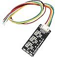
The 4S 1.2A Li-ion Lipo Lifepo4 Battery Active Equalizer Balancer is a small and compact addition to a DIY battery to ensure cells are kept in balance without the need of an additional BMS board.There are 3 red LEDs at the bottom of the board (farthest from the connector) that illuminate whenever the board is balancing. Each led represents power going between specific cells in the battery.I paired this board with a 100 watt bidirectional tpye C charging board. The type C board does not have any balance function but it does have over-charge and over-discharge protection.Typically, to make sure the battery does not get out of sync with itself you would need to add a dedicated BMS to balance the cells.This board eliminates the need for a full BMS by adding the balance function to the batteries without the complexity of adding charge and discharge protection.
I**D
Expensive, laughed at only two balancings.
Worked initially. Very very finicky. While connecting at minor contact shock, fried the board.
P**B
This balances my 5S 18650 packs perfectly
I've had some DeWalt batteries that seem to get out-of-balance with age, or more recently, TWO 2-year old packs...(I suspect they are counterfeit, even though they have all the "legit" markings of DeWalt) I soldered the balance leads to Pomona clips, and I just take the battery top cover off, and attach the clips to each cell. When I'm satisfied that everything is connected right, I plug in the balance plug to the jack on this board, and it goes to work. It has brought back batteries that won't charge or run my drill to (seemingly) full function.
Trustpilot
1 month ago
5 days ago
1 day ago
3 weeks ago